Compared with traditional vehicles, the structure of new energy vehicles is mainly divided into low-voltage power consumption part and high-voltage power consumption part. The low-voltage power consumption part is powered by auxiliary batteries, and the power supply voltage is generally 12-14V, which is mainly used for instrument panel display, lighting, body VCU memory, sensors, relays, electronic audio system and anti-theft alarm system, etc.; the high-voltage power consumption part is powered by power battery packs, which is mainly used for high-voltage management power supply system, drive motor system, air conditioning and warm air heating system of new energy vehicles, etc. This article describes the key components and functions of new energy vehicles in detail.
I. Definition of new energy vehicles
General terms for new energy vehicles include pure electric vehicles, hybrid electric vehicles, and fuel cell electric vehicles.
Pure electric vehicles refer to vehicles driven by motors whose driving energy is completely provided by electric energy. The driving electric energy of the motor comes from the on-board rechargeable energy storage system or other energy storage devices.
Hybrid electric vehicles can obtain power from at least two types of on-board stored energy: consumable fuel and rechargeable energy/energy storage devices.
Fuel cell electric vehicles are electric vehicles that use fuel cell systems as the sole power source or use fuel cell systems and rechargeable energy storage systems as hybrid power sources.
II. Key Components and Functions
(1) High-voltage Marking Warning marks are affixed to the case of high-voltage components of new energy vehicles. Maintenance personnel can recognize at a glance that this component may bring high voltage dangers through the mark. Since the high-voltage connecting cable needs to connect the high-voltage components at both ends and is relatively long, it is not eye-catching to use warning marks on the high-voltage cable to remind maintenance personnel, and these warning marks may be ignored. Therefore, the high-voltage connecting cable, including the plug and the maintenance switch, is orange to serve as a reminder.
(2) High-voltage connecting cable New energy vehicles generally have two high-voltage busbars, namely the positive busbar and the negative busbar, coming out of the power battery pack to connect the power battery pack of the new energy vehicle and the motor controller of the vehicle. First, it passes through the high-voltage distribution box (PDU) system (with integrated high-voltage distribution box and on-board charger), and then passes through the power control unit (with integrated DC/DC converter and motor controller) to supply power to the drive motor system; it is divided into several routes to supply power to the air-conditioning compressor and PTC heating controller.
The main function of the high-voltage connecting cable is to safely provide current after the power battery pack is connected through the safety box, and the safety standards for high voltage must be followed. In many hybrid vehicles, the DC cable assembly extends from the rear of the vehicle (where it is connected to the vehicle’s hybrid battery pack) to the motor controller under the vehicle’s engine hood. Since most of the high-voltage connection cable is located under the vehicle chassis (sandwiched between the power battery pack and the chassis), it is well protected from damage caused by collisions with the road surface. The battery packs installed in pure electric vehicles and some plug-in vehicles are much larger and often extend to the front of the vehicle, so their high-voltage connection cables are usually shorter than those in hybrid vehicles.
(3) High-voltage connectors High-voltage connector cables connect high-voltage components, which are not only key energy transmission components for vehicle driving, but also key factors affecting vehicle safety performance. If the connector is not connected or loose, it may cause the vehicle to break down, catch fire, or even cause electric shock. Therefore, the prescribed sequence must be strictly followed when loosening or fixing the high-voltage connector.
Taking the Geely Emgrand EV450 model as an example, the first type of high-voltage connector is the HVP800 series. The plug-in and unplug methods of this type of connector are as follows:
Move the red buckle of the power handle backwards with your hand or a screwdriver.
When the red buckle is detached from the paint mark, slowly pull the power handle upwards and the connector will be removed.
When the power handle reaches the vertical position, the connector will be completely pulled out.
The order of plugging in and pulling out the high-voltage plug-in is opposite.
The second type of high-voltage connector is the HVA280 series. The plug-in and pull-out method of this type of connector is as follows:
After pressing the red lock, pull the red lock backward until it is detached from the paint mark.
After pressing down the circled position in the figure, the connector can be pulled out.
The order of plugging in and pulling out the high-voltage plug-in is opposite.
Note: Because it is a high-voltage connector, it is necessary to pay attention to “one plug, two rings, and three confirmations” when plugging.
(4) When repairing or replacing high-voltage components, the high-voltage system must be cut off to a voltage-free state through the standard power-off process, that is, first turn off the ignition switch (wait for at least 5 seconds), and then pull out the high-voltage maintenance switch.
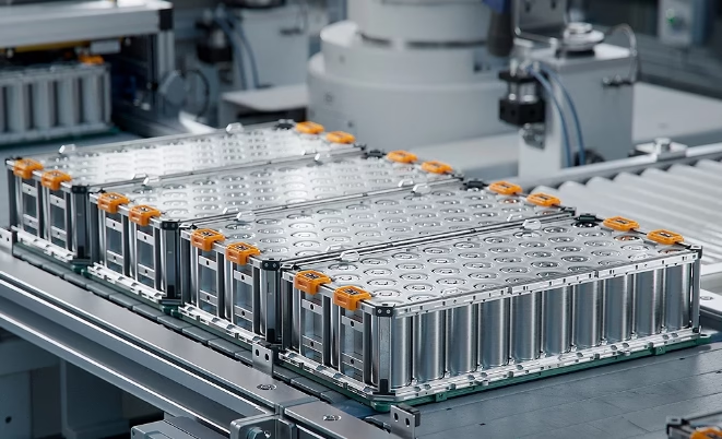
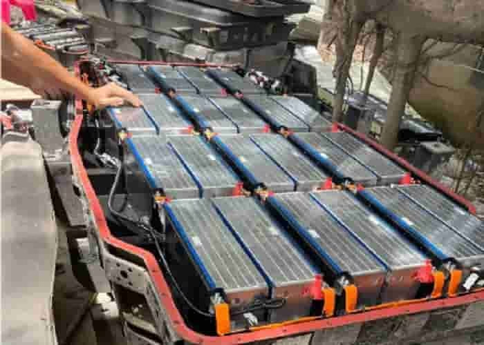
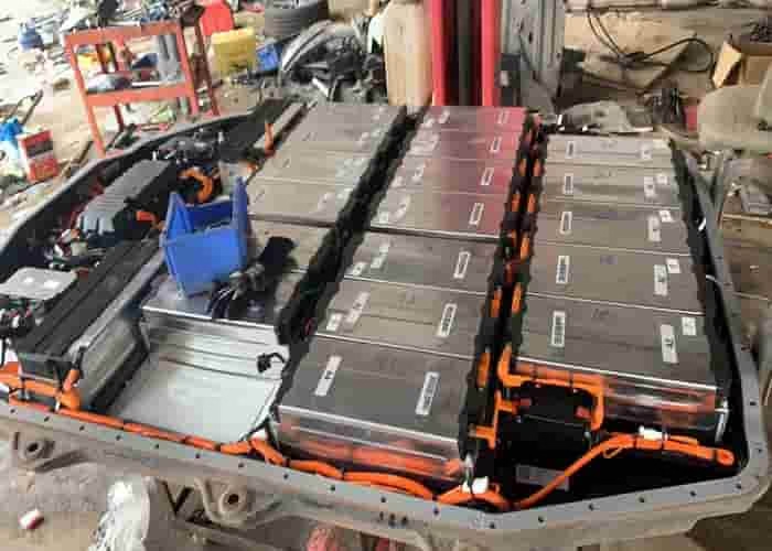
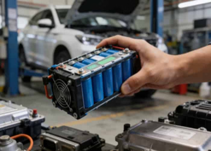
(5) Power battery pack The power battery is one of the core components of new energy vehicles. It is equivalent to the fuel tank of an internal combustion engine-driven vehicle and is an energy storage device for the electric drive unit. The battery must store sufficient electrical energy capacity.
The power cell group is mainly composed of various module assemblies, battery information acquisition system, battery control unit (BMU), high-voltage safety box (B-BOX) and other components. The power battery pack assembly is installed in the lower part of the vehicle body and encapsulated in the box. The function of the power battery box is to carry and protect the power battery pack and its internal electrical components, so it has high strength and rigidity and is dustproof and waterproof. The protection level of the battery box is IP67.
(6) Battery management system The function of the battery management system (BMS) is to monitor the status of the battery (temperature, voltage, remaining power), provide communication, safety, single cell balancing and management control for the battery, and provide a communication interface with the application equipment. The battery management system can perform charge and discharge control, power on and off control, SOC/SOH (state of charge/battery capacity) estimation, fault diagnosis and processing, thermal management, power control, BMU (battery management unit) management, balancing management, electrical damage management, etc. It also has the function of monitoring battery status and communicating with other management modules through CAN signals. The battery management system is mainly composed of battery modules, battery information acquisition units, battery management units, thermal management systems, sampling lines, high-voltage relay boxes and communication systems.
The main function of the battery information collector (CSC) is an electronic device that collects or monitors the electrical and thermal data of single cells or modules, including the balancing of single cells; the acquisition system reports the relevant information to the battery manager through the sampling line (including sensors) and performs single cell voltage balancing according to the instructions of the battery manager. The battery manager (BMU) is the core component of the battery management system, which mainly controls, manages, detects or calculates the electrical and thermal parameters of the battery system, and provides an electronic device for communication between the battery system and other vehicle controllers. It mainly realizes charge and discharge control, power on and off control, SOC/SOH estimation, fault diagnosis and processing, thermal management, power control, BMU management, balancing management, etc.
(7) High-voltage safety When a high-voltage system fails, the high-voltage safety box disconnects the output of the high-voltage battery in time to protect the high-voltage circuit and components. The high-voltage safety box is installed at the positive and negative output ends of the power battery assembly and consists of a high-voltage positive contactor, a high-voltage negative contactor, a pre-charge contactor, a current sensor, and a pre-charge resistor.
Two of the contactors are installed in parallel on the positive or negative side of the circuit between the power battery pack and the motor controller. One is the pre-charge contactor and the other is the high-voltage main contactor.
When the vehicle is powered on, in order to protect the high-voltage circuit, the pre-charge contactor is first closed through the contact resistor (current limiting) to connect the power battery pack to the motor controller. At the same time, the power battery pack charges the motor controller capacitor. When a function self-test of the high-voltage management system fails, the pre-charge contactor will be disconnected immediately and a fault code will be generated. If all system self-tests can pass and the capacitor is fully charged (reverse injection voltage ≤ 50V), the high-voltage main contactor is closed and the pre-charge contactor is disconnected, and full current power-on begins. If the vehicle is powered off or the vehicle’s high-voltage drive system issues an emergency stop command, the high-voltage main contactor will disconnect immediately or after a few seconds, forcibly disconnecting the power battery pack from the high-voltage circuit.
(8) High-voltage distribution system The high-voltage distribution system uses the power battery to provide energy for high-voltage components such as the motor controller (PEU), drive motor, air conditioning compressor, and warm air heater (PTC). The power battery also needs to be recharged by the DC charging or AC charging system. All high-voltage components are connected and transmit power by the high-voltage distribution system.
(9) Motor control system The motor control system consists of two parts: a DC/DC converter and a motor controller. The function of the DC/DC converter is to convert high DC power into low-voltage DC voltage and provide 13.8V power for the vehicle’s low-voltage system, similar to the function of a traditional automotive generator. The motor controller is generally installed in the engine compartment. The motor control system communicates with other vehicle controllers through CAN signals. It is a device that controls the energy transfer between the power supply and the motor. It consists of a control signal interface circuit, a motor control circuit, and a drive circuit. The motor controller is directly connected to the DC high-voltage end of the vehicle and directly connected to the three-phase end of the drive motor, and has a high-voltage interlocking function.
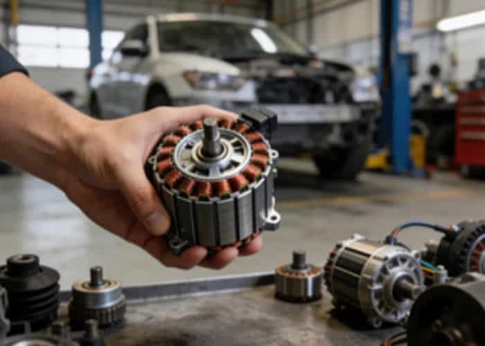
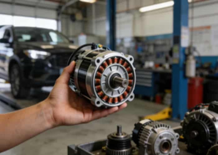
(10) Drive motor The drive motor is installed at the lower part of the vehicle body. The drive motor is a permanent magnet synchronous motor that provides driving force for the vehicle. Its power characteristics determine the main performance indicators of the vehicle. The power is mainly affected by the road conditions (flat road, uphill, downhill), the maximum speed and the acceleration of the vehicle. The drive motor system is mainly composed of the drive motor, the motor controller and its auxiliary devices necessary for work.
(11) Charging system The charging system is divided into four items from the system perspective: DC charging, AC charging, 12V charging, and brake energy recovery.
The DC charging system consists of the following components: DC charging pile, DC charging gun (with high-voltage connection cable), DC charging socket, power battery, and off-board charger. The DC charging socket is installed at the left rear position of the vehicle body. It can receive power from the DC charging pile and transmit power to the power battery for charging through the high-voltage connection cable.
The AC charging system consists of the following components: AC charging pile, AC charging gun (with high-voltage connection cable), AC charging socket, power battery, and on-board charger. The AC charging socket is installed at the left front position of the vehicle body. It can receive the power of the AC charging pile and transmit the power to the on-board charger through the high-voltage connection cable. The on-board charger converts the AC power into DC power and then transmits it to the power battery for charging.
The 12V charging function is realized by the following components: 12V battery, DC-DC converter, power battery.
The braking energy recovery function is realized by the following components: brake switch, power battery, drive motor, vehicle controller, high-voltage connection cable, etc.
(12) Air conditioning and heating system The air conditioning and heating system is generally installed in the engine compartment. It uses a high-voltage electric air conditioner. The electric compressor is used for the refrigeration cycle. Its main function is to compress the low-temperature and low-pressure gas from the evaporator into high-temperature and high-pressure gas to provide source power for the entire refrigeration system. Unlike traditional cars, the heating system of new energy vehicles uses PTC heating wire for heating. When the air conditioning system is started, the power battery supplies high voltage power to the PTC to generate heat.
Whether the high-voltage components on new energy vehicles are used to drive the vehicle or to control the air conditioning or heating functions, what these components have in common is that they all operate at high voltage. When servicing them, you must be familiar with the structure and location of the high-voltage components.


Leave a Reply